Microtron

The Forty Year History of a Microtron Robot

  • About Microtron

A/D & Inverter Circuits

Posted by site owner on January 20, 1982
Posted in: History, logbook, Programming.

Completed the Analog-to-Digital Converter and associated Inverter Circuit. The A/D Converter is so that Mike’s on-board microcomputer can detect the position of the directional detector potentiometer, as well as read the joystick. The Inverter Circuit is needed because all output lines on the KIM-1 go high (ie, to 1) when ‘reset’ is pressed-so the programs will output 0 for high, 1 for low and the TTL lines will be inverted.

Posts navigation

← Directional Control Potentiometer
Joystick →
  • Additional Pages

    • About Microtron
  • Categories

    • brain functions
    • Hardware
    • History
    • logbook
    • photos
    • Programming
  • Log entries

    June 2025
    S M T W T F S
    1234567
    891011121314
    15161718192021
    22232425262728
    2930  
    « Feb    
  • Organizations

    • Boston Robotics Group
    • Connecticut Robotics Society
    • Society of Robots
  • Other Microtron Robot Sites

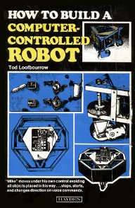
    • "How to build a computer-controlled robot" (amazon) "How to build a computer-controlled robot" (amazon)
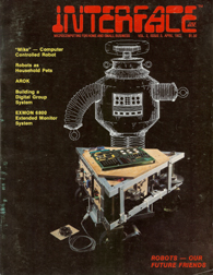
    • 1976 – "Microtron" at Cybernetic Zoo
    • 1977 Interface Age Article (pdf) 1977 Interface Age Article (pdf)
    • Eric's Review of the Book (KIM User Notes)
    • S.A.M. (another Microtron based robot)
    • Servo's 2008 review
    • Where Have All the Robots Gone? (Servo, 2004)
  • Retail sites

    • 'Brainstem' brand controllers
    • Phidgets
    • Robot Electronics
    • Robotics Connection
    • RobotShop
    • Trossen Robotics Robot Controllers
    • ZagrosRobotics ZagrosRobotics
Proudly powered by WordPress Theme: Parament by Automattic.


www.daughterofkrypton.com